Quick Look
Grade Level: 10 (9-11)
Time Required: 1 hour
(Note: Time depends on level of prior coding experience)
Expendable Cost/Group: US $0.00
Group Size: 2
Activity Dependency: None
Subject Areas: Computer Science, Science and Technology
NGSS Performance Expectations:

| HS-ETS1-2 |
Summary
This is a series of short activities that introduce students to physical computing, where they will use a basic breadboard, an Arduino Uno, and components to code and run a single and double LED, a buzzer, and a touch sensor. After successfully coding and wiring the individual components, they have the choice to either set up a realistic traffic light or a buzzer activated by a touch sensor.Engineering Connection
Physical computing involves interactive systems that can sense and respond to the world around them. Engineers can use various types of sensors wired to a microcontroller such as an Arduino to solve problems. For example, if plants in a greenhouse need to be kept in a well-lit environment, an engineer could set up a light sensor to detect light below a certain threshold and set off a buzzer to alert the greenhouse worker to turn on the lights.
Learning Objectives
After this activity, students should be able to:
- Construct a functional electrical circuit using an Arduino, a breadboard, and other electrical components.
- Set up a program that will integrate the input from a touch sensor with an output from an LED and buzzer.
- Modify the code to change the output of the LED and buzzer (in terms of length and intensity of signal).
- Apply the physical computing setup created in this activity to a real-life situation.
Educational Standards
Each TeachEngineering lesson or activity is correlated to one or more K-12 science,
technology, engineering or math (STEM) educational standards.
All 100,000+ K-12 STEM standards covered in TeachEngineering are collected, maintained and packaged by the Achievement Standards Network (ASN),
a project of D2L (www.achievementstandards.org).
In the ASN, standards are hierarchically structured: first by source; e.g., by state; within source by type; e.g., science or mathematics;
within type by subtype, then by grade, etc.
Each TeachEngineering lesson or activity is correlated to one or more K-12 science, technology, engineering or math (STEM) educational standards.
All 100,000+ K-12 STEM standards covered in TeachEngineering are collected, maintained and packaged by the Achievement Standards Network (ASN), a project of D2L (www.achievementstandards.org).
In the ASN, standards are hierarchically structured: first by source; e.g., by state; within source by type; e.g., science or mathematics; within type by subtype, then by grade, etc.
NGSS: Next Generation Science Standards - Science
| NGSS Performance Expectation | ||
|---|---|---|
|
HS-ETS1-2. Design a solution to a complex real-world problem by breaking it down into smaller, more manageable problems that can be solved through engineering. (Grades 9 - 12) Do you agree with this alignment? |
||
| Click to view other curriculum aligned to this Performance Expectation | ||
| This activity focuses on the following Three Dimensional Learning aspects of NGSS: | ||
| Science & Engineering Practices | Disciplinary Core Ideas | Crosscutting Concepts |
| Design a solution to a complex real-world problem, based on scientific knowledge, student-generated sources of evidence, prioritized criteria, and tradeoff considerations. Alignment agreement: | Criteria may need to be broken down into simpler ones that can be approached systematically, and decisions about the priority of certain criteria over others (trade-offs) may be needed. Alignment agreement: | |
Common Core State Standards - Math
-
Interpret expressions that represent a quantity in terms of its context
(Grades
9 -
12)
More Details
Do you agree with this alignment?
Materials List
Required for each student or pair of students:
- laptop with USB port
- Arduino Uno
- USB 2.0 cable type A/B
- 3 LEDs (red, yellow, and green)
- 1 100 ohm resistor
- 3 220 ohm resistor
- breadboard
- 5 multicolor jumper wires
- Piezo buzzer
- touch sensor
- worksheets (one per student):
To share with the class
- laptop/computer with Internet access and projector
Worksheets and Attachments
Visit [www.teachengineering.org/activities/view/bos-2831-touch-sensor-arduino-trigger-led-buzzer] to print or download.Pre-Req Knowledge
This series of short lessons does not require prerequisite knowledge of coding or circuits. It starts at a very basic level and allows students to first copy code and then make small modifications. All of the coding and circuits are taught through short, guided practice.
Introduction/Motivation
Who has heard of the Internet of Things (IoT)? (Let students offer suggestions.) Let’s take a look at this video clip: What is the Internet of Things? (1:41 minutes).
What is an Arduino? (Let students offer suggestions.) What do you think Arduinos are used for? (Let students offer suggestions. Show video clip [5:51 minutes]: What's an Arduino // Maker101 | I Like To Make Stuff.)
What is a breadboard? Let’s check out this tutorial with helpful images: https://learn.sparkfun.com/tutorials/how-to-use-a-breadboard/all#introduction
Here’s what a mini breadboard looks like. (Show Figure 1, a photo of the back of a mini breadboard showing where metal connections are vertical in columns and horizontal in rows [right breadboard was created by removing the sticker from the underside of a mini breadboard.]) 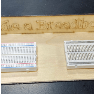
How does tapping an AirPod control its function? (Let students offer suggestions.) (Answer: Code in settings on the phone causes the taps to trigger a touch sensor and then turn the sound on/off, etc.)
How is controlling an AirPod different from using an Arduino to turn on an LED and a buzzer? (Answer: The AirPod is controlled through a Bluetooth connection, which is a more advanced way to use the Arduino wirelessly.)
So, what have we learned about physical computing? (Answer: It’s the use of tangible, embedded microcontroller-based interactive systems that can sense the world around them and/or control outputs such as lights, displays, and motors.)
What other ways can you think of where touch sensors are used in our everyday lives? (Examples: touch screens on iPads, laptops, credit card payment machines at stores, phone-capacitive touch, not just contact, opening a handicap-accessible door (requires more pressure), some faucets, soap dispensers, and paper towel dispensers. For health reasons, many devices have proximity sensors which do not require contact.)
Today we are going to go through a series of short activities that introduce you to physical computing. You will be using a basic breadboard, an Arduino Uno, and components to code and run a single and double LED, a buzzer, and a touch sensor. After successfully coding and wiring the individual components, you will then have the choice to either set up a realistic traffic light or a buzzer activated by a touch sensor.
First you will learn how to code a single LED to flash on and off, then now to code two LEDS blinking opposite each other, and then you will then wire and program a buzzer to sound, and you have seen that a touch sensor can detect the touch of a finger and cause an LED to go on.
Once you have accomplished the separate tasks, you will choose between two challenges that each give you the chance to combine elements in the circuit and coding. The first option is a little simpler and will require you to create a model of a traffic light that will require the right colors and order of lights going on and off. As you learn to drive a car, you will probably notice the sequence and length of the traffic lights even more closely.
The second option is a little more difficult and requires you to set up a system that will respond to the touch of a finger by turning on a light and sounding a buzzer. This could be helpful in many situations where a person needs to get help, similar to a Lifetouch button that an elderly person wears around their neck in case they fall and need to get help.
Procedure
Background
Physical computing involves using technology that can interact with and respond to external stimuli (e.g., using an Arduino, touching a touch sensor could lead to a buzzer being set off). In this activity, students wire an Arduino into a breadboard with various sensors and components. Tutorials on the Arduino UNO are available here: https://www.arduino.cc/en/Tutorial/HomePage.
Before the Activity
- Make sure all materials are laid out in the classroom.
- Make sure to have all worksheets printed for students (one per student).
- Run through the activities to be familiar with their procedures.
With the Students
- Read through the Introduction/Motivation section.
- Part 1: Introduction to the Arduino and Breadboarding
- Note: If students are familiar with Arduinos and breadboards, you can skip this lesson and move to Step 4/Part 2.
- Distribute the Part 1: Introduction to Arduino and Breadboarding Worksheet to students.
- Tell the students: First we will learn about how physical computing works, where electrical components can be wired and coded to do things like turn on a light or make a sound. Then you will download the Arduino program to your computer and set up a Google folder on the desktop to save your code after each of the short lessons we will be completing with the Arduino in this unit.
- Have students get their materials: laptop with USB port, Arduino Uno, and USB 2.0 cable type A/B.
- Have students view the videos to introduce the Arduino and breadboard; these are listed in the Part 1: Introduction to Arduino and Breadboarding Worksheet and below:
- https://www.youtube.com/watch?v=QvyTEx1wyOY&authuser=0 (5:34 minutes)
- https://www.youtube.com/watch?v=OAx_6-wdslM&authuser=0 (1:20 minutes)
- https://www.youtube.com/watch?v=NYzN0a1U8mI&authuser=0 (1:26 minutes)

- Note: As students complete Parts 2-6 of this activity, walk around with the Arduino Grading Sheet to monitor student progress and grade. Two aspects can be assessed: whether the student could properly wire and control the required components and whether the code worked properly. Students will work at different paces, so when a student has completed a part, you can give them the next part to work on.
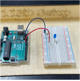
- Part 2: Arduino LED Blink
- Tell the students: In this activity you will construct a circuit and program the Arduino to turn an LED on and off. The goal is to have the LED flash on and off and modify the length of time this takes.
- Have students get their materials: Part 2: Arduino LED Blink Worksheet, Arduino with computer and cords, one LED, one 220 ohm resistor, a mini breadboard, and two jumper wires.
- Have students follow the instructions on Part 2: Arduino LED Blink worksheet.

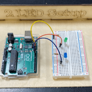
- Part 3: Arduino 2 LEDs Blink
- Tell students: In this activity you will construct a circuit and program the Arduino to turn two LEDs on and off opposite each other. The goal is to have the two LEDs flash on and off, alternating with each other, and try modifying the length of time each one stays on and off. (Note: In this part, students are challenged to wire two LEDs in the breadboard and code them so that they alternate in blinking. You will have access to the answer key to help students who have difficulty in the coding or hardwiring part.)
- Have students get their materials: Part 3: Arduino LED Blink Worksheet, Arduino with computer and cords, two LEDs, two 220 ohm resistors, mini breadboard, and three jumper wires.
- Have students follow the instructions on Part 3: Arduino LED Blink Worksheet.
How does a traffic light work?
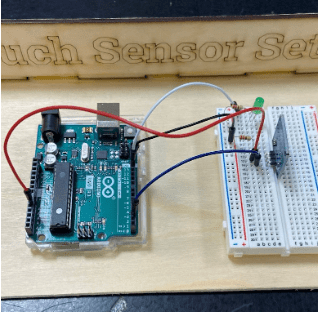
- Part 4: Arduino Touch Sensor
- Tell students: In this activity you will construct a circuit and program the Arduino to connect the touch sensor and a single LED. The goal is to have the LED flash when you place your finger on the touch sensor.
- Have students get their materials: Part 4: Arduino Touch Sensor Worksheet, Arduino with computer and cords, one LED, two 220 ohm resistors, mini breadboard, touch sensor, and four jumper wires.
- Have students follow the instructions on Part 4: Arduino Touch Sensor Worksheet.
- Part 5: Arduino Buzzer
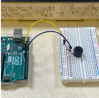
- Tell students: In this activity you will construct a circuit and program the Arduino to connect a Piezo buzzer. The goal is to have the buzzer sound after the code has been downloaded to the Arduino.
- Have students get their materials: Part 5: Arduino Buzzer Worksheet, Arduino with computer and cords, one 100 ohm resistor, mini breadboard, Piezo buzzer, and two jumper wires.
- Have students follow the instructions on Part 5: Arduino Buzzer Worksheet.
- Part 6: Arduino Challenges
- Note: For this part, students use what they have learned from the various tutorials to engage in a coding and hardwiring challenge. Students have the option of completing a traffic light challenge, where they must have three LEDs (red, yellow, and green) and code them so that they go on for a certain time frame and then off when another turns on. Use the Part 6A: Arduino Traffic Light Challenge Answer Key to aid in student support. The second option students have is to hardwire and code a touch-sensor buzzer. Use the Part 6B: Arduinos Touch Controlled Buzzer Challenge Answer Key to aid in student support as well.
- Allow students a moment to choose which challenge they will complete.
Option #1: Part 6A Arduino Traffic Light Challenge
- Tell students: In this activity you will construct a circuit and program the Arduino to connect three LEDs and get them to go on and off in sequence to model a traffic light. The goal is to use your code from and wiring from previous activities to complete the challenge.
- Have students get their materials: Part 6A: Arduino Traffic Light Challenge Worksheet, Arduino with computer and cords, three LEDs (red, yellow, and green), three 220 ohm resistors, mini breadboard, and four jumper wires.
- Have students follow the instructions on Part 6A: Arduino Traffic Light Challenge Worksheet.
Option #2: Part 6B Arduinos Touch Controlled Buzzer Challenge
- Tell students: In this activity you will construct a circuit and program the Arduino to connect the touch sensor, LED, and buzzer. The goal is to have the LED flash and buzzer sound when you place your finger on the touch sensor.
- Have students get their materials: Part 6B: Arduinos Touch Controlled Buzzer Challenge Worksheet, Arduino with computer and cords, one LED, one 100 ohm resistor, two 220 ohm resistors, mini breadboard, Piezo buzzer, touch sensor, and five jumper wires.
- Have students follow the instructions on Part 6B: Arduinos Touch Controlled Buzzer Challenge Worksheet.
- Wrap Up/Reflection: After students have completed their challenge successfully, give students the wrap-up question: How could engineers use different sensors and electronic components to solve other problems? See the Engineering Connections Post-Activity Assessment for more information.
Vocabulary/Definitions
electrical circuit: A path for transmitting electrical current.
LED: Light emitting diode; a semiconductor light source that emits light when current flows through it.
loop function: After creating a setup() function, which initializes and sets the initial values, the loop() function does precisely what its name suggests, and loops consecutively, allowing a program to change and respond. Used to actively control an Arduino board.
physical computing: The use of tangible, embedded microcontroller-based interactive systems that can sense the world around them and/or control outputs such as lights, displays, and motors.
Piezo buzzer: A type of electronic device that is used to produce a tone, alarm, or sound.
resistor: An electrical component that limits or regulates the flow of electrical current in an electronic circuit.
setup function: Called when a sketch starts. Used to initialize variables or pin modes, start using libraries, etc. The setup() function will only run once, after each power-up or reset of the Arduino board.
touch sensor: A type of device that captures and records physical touch on a device and/or object.
Assessment
Pre-Activity Assessment
Intro to Arduino: The pre-activity is Part 1. In this section, students download the software needed for Arduino and learn how an Arduino works. Students will also gain exposure to what a breadboard is.
Activity Embedded (Formative) Assessment
Arduino Tutorials: In Parts 2-5, students learn how to wire different sensors into a breadboard and how to manipulate code to customize the sensors for the challenge. Walk around with the Arduino Grading Sheet to monitor student progress and grade.
Post-Activity (Summative) Assessment
Arduino Challenges: In Part 6, students have the option to either design a traffic light or a touch sensor buzzer. Students use what they have learned from the various tutorials to engage in their chosen coding and hardwiring challenge. Walk around with the Arduino Grading Sheet to monitor student progress and grade.
Engineering Connections: Have a class discussion of the activity, giving students a chance to show connections to the engineering design process and applications of the activity to solve real-world problems. Ask students: How could engineers use different sensors and electronic components to solve other problems? Alternatively: Provide each pair/group with an example of a sensor and have them come up with a way sensors and components could be used to solve a problem. This may help them apply what they know more effectively. (Optional: There are sets of sensors available that could even be passed out for students to handle and better visualize the setup.)
Possible responses:
Magnetic sensor—when magnetic dog door is opened, it could cause a buzzer to go off to alert the owner that the dog has gone through.
Moisture sensor—when moisture sensor detects low moisture in a houseplant, a light could go on to alert the homeowner to water the plant.
Sound sensor—the sound sensor could be coded to detect a baby crying to let the caregiver know the baby is awake and crying.
Push button—the push button could trigger a buzzer such as a doorbell, producing a sound to alert the homeowner that someone is at the door.
Gas sensor—a gas sensor could be coded to detect carbon monoxide and trigger a buzzer and light.
Temperature sensor—the temperature sensor could be coded to detect a rise in temperature in the prep room of our classroom where the 3D printers are located. If an alarm goes off, we will know to turn on the fans to cool off the area.
Light sensor—if the light sensor detects light below a certain level, a light or buzzer could go off to alert the greenhouse worker to turn on the lights for the plants, or the lights could be programmed to turn on automatically.
Safety Issues
Students should only connect components as instructed. Connecting in other ways could result in electrical shock, fire, or damage to equipment.
Troubleshooting Tips
When undertaking physical computing, there are many ways things can go wrong. Problem-solving with a partner and testing out coding, wiring, and individual components can all help students deductively reason what is and is not the cause of a malfunction. Having extra components is helpful to rule out faulty equipment.
Activity Extensions
- Students could learn how to program a motor to turn on in response to the touch sensor.
- Students could set up a Bluetooth connection so the system could work wirelessly.
- Students could try out other sensors and come up with ways to program them with the Arduino and solve problems.
Activity Scaling
For more advanced students:
- If students have had experience with coding, Arduinos, and breadboards, they can start at Part 2. If students are advanced, they can go straight to the engineering design challenge, which is Part 6.
Subscribe
Get the inside scoop on all things TeachEngineering such as new site features, curriculum updates, video releases, and more by signing up for our newsletter!Copyright
© 2024 by Regents of the University of Colorado; original © 2023 Boston UniversityContributors
Susan West, Science and Engineering Teacher at Barnstable High School, Hyannis, MA Shereen Mejia, East Boston High School, Boston MASupporting Program
NSF Research Experience for Teachers (RET) in Integrated Nanomanufacturing at the Photonics Center, Boston UniversityAcknowledgements
This curriculum was based upon work supported by the National Science Foundation under RET grant no. EEC 1407165—at the Research Experience for Teachers in Integrated Nanomanufacturing at the Photonics Center at Boston University. Any opinions, findings, and conclusions or recommendations expressed in this material are those of the authors and do not necessarily reflect the views of the National Science Foundation.
Last modified: June 13, 2024



User Comments & Tips